CHAPTER 3
ALIGNMENT
3.1 Introduction
The spatial distribution of the intensity I(r) of a collimated Gaussian laser beam is given by:
I(r) = I0 exp (-2r2 / r0 2)
r is the radial distance from the center of the beam and r0 is the radius at which the irradiance has fallen the 1 / e2 of its value I0 at the center of the beam. The distribution will ramain Gaussian at all distances from the laser. The divergence angle ‘ q ‘ for a Gaussian beam is given by
q = 2 l / p D
where l is the wavelength and D the diameter of the exit-aperture of the laser. ‘ q ‘ is the measure of the half-angle of the cone into which the beam diverges at distances far from laser.Typical value of ‘ q ‘ for a He – Ne laser is of the order 10–3 rad and this value can be reduced further with external collimating optics. This excellent collimation of the beam coupled with high radiance of a He – Ne laser (orange – red beam of a He – Ne laser is easily visible, even in ambient background of room light or sunlight ) allows the determination of the precise position, linear as well as angular, of the objects at positions remote from the laser, making lasers valuable tools in a checking the alignment. Alignment of huge structures like aircrafts, tunnels, pipelines, shafts, railroad tracks, bridges etc can be easily measured to very high accuracy. Again the alignment check can be carried out while the product is being fabricated/assembled.
3.2 Laser-Based Alignment System
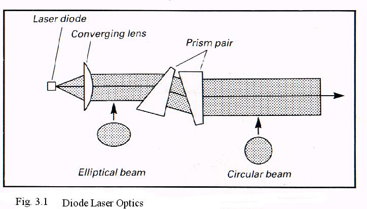
A typical laser based system to check the alignment consists of (i) a laser and beam collimating optics,(ii) a position sensitive detector and (iii) a display system and/or computer. As mentioned earlier, He – Ne has very low divergence ( ~ 10 –3 mrad ) and the beam can be further collimated using beam expanders which are easily available. However, He–Ne is usually large in physical size ( » 12 inches) and may be cumbersome to use in a certain applications. On the other hand a diode laser is a smaller device, but requires additional optics to structure its elliptical beam into circular beam. This is achieved by using a converging lens and a pair of the prisms (Fig 3.1). A cylindrical lens also can be used in place of the prisms.
Several types of detectors are available for the detection of position of the laser beam. These are:
3.2.1 Quadrant Photodiode
A quadrant photodiode consists of four photodiodes arranged in four quadrants of a circular structure. These photodiodes are electronically connected in quadrature to compare the intensity in each half of the beam, both horizontally and vertically. There is null signal from the quadrant photodiode when all the four quadrants receive same amount of light. If the beam is displaced from the center, we get the output from the quadrant photodiode. This output is the measure of the displacement of the beam and the sign of the output indicates the direction of displacement. To get accurate measurements the laser beam should be Gaussian.
3.2.2 Lateral–Effect Photodiode
It is a PIN silicon photodiode with metallic contacts separated by distance L. As a spot of light is scanned across the interelectrode spacing the fraction of the current carried by each electrode varies. The current "I" carried by one of the electrodes when a spot of light is at a distance x from that electrode is given by:
I = I0 sinha (L-x)/ sinha L
Where I0 is the total photocurrent and a is a material parameter.
When x = 0, I = I0 all the current is cerried by that electrode.
When x = L, I = 0 all the current is cerried by other electrode.
The displacement is the laser beam can be measured by monitoring the current through one of the electrode.
3.2.3 Photo–Diode Arrays
Arrays of photo – diodes can provide a simple indication of the location of the laser beam through the observation of which diodes are illuminated. Two dimensional arrays with hundreds of diodes in each combination are commercially available.
3.2.4 Image Dissector Tubes
It is photomultiplier tube which include an electrostatic field that focuses the photoelectrons from the photocathod, an aperture for the electron beam and deflection system that allows one to steer the beam through the aperture. The measure of the deflection required to steer the beam through the aperture gives the position of the laser spot an the photocathod, makeing the measurement of displacement of the light beam possible.
3.2.5 Vidicon
In a vidicon photosensitive surface is a photoconductive rather than photoemssive. The electrical charge level of the photosensitive surface is function of the intensity of the light falling on the surface. A scanning electron beam is used to measure the level of the electrical charge on the photosensitive surface. Thus information about the position of the beam is obtained.
Quadrant photodiodes and lateral – effect photodiodes are used to check one dimensional alignment while photodiode arrays with a computer are generally for two dimensional alignment check.
3.2.6 System to Check Angular Alignment

Angular alignment can be checked using a converging lens as shown in Fig. 3.2. Laser beam is originally centered on a leteral – effect photodiode or a diode array without the lens. On insertion of a lens of focal length ‘f ‘ the focused beam shifts by fq which is the measure of angular alignment. For example , if one has to drill holes as per the given standard, a laser is mounted on the spindle holding the drill and detector is placed on the standard, so that while drilling each drill can be checked with the standard.
3.3 Typical Examples
(a) To check the alignment of large stuctures like a jet aircraft. Again this is done while manufacturing with an accuracy of ± 0.002 inch over a distace of about 200 feet.
(b) The straightness of the machine can be checked to ensure that the parts are being manufactured as per given standards. For example straightness of the motion of a boring mill with a 22.5 feet bed can be checked with an accuracy of 0.0005 inch.
(c) Shaft – to – shaft alignment in which two rotating shafts are aligned so that the directions of the shaft centerlines are parallel. This involves the measurements of four angles, two perpendicular components for the angle each shaft centerline makes with line between two shafts. With the help of a laser based alignment system the alignment with an accuracy of 0.001° can be checked.
(d) The straightness of tunnels of rapid transit system in USA could be ensured to the accuracy of one inch over a 1.5 mile span . Similarly a 3 Km long linear accelerator could be aligned to an accuracy of 0.5mm over a 3Km range. Such tolerance cannot be checked with conventional systems.
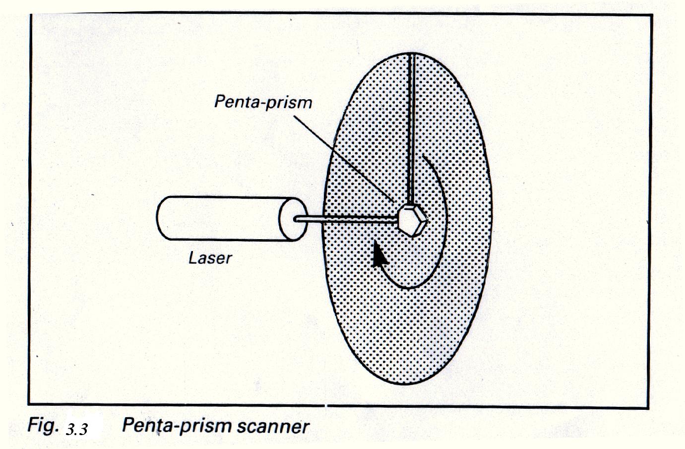
(e) A flat surface can be absolutely graded by using a laser beam which scans out a horizontal plane a position detector system used to detect the beam reflected from the surface. A rotating penta prism is used to turn a laser beam to sweep a flat surface (Fig. 3.3). The quality of road beds is cheaked by such a system. Again it is an ‘on-line’ measurement as the position detector can be mounted on the earth-moving equipment to control the movement of such equipment.