
Download pdf
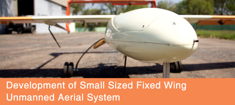
PI: Professor A.K. Ghosh, Department of Aerospace Engineering Co-PI: Professor Deepu Philip, Department of Industrial and Management Engineering Professor J. Ramkumar, Department of Mechanical Engineering Sponsor: IIT Kanpur and Prabhu Goel Foundation The project aimed at developing a small sized Unmanned Aerial System (UAS) based on the fixed wing platform, having long endurance, in a pusher configuration; capable of both civil and defense applications. The platform was chosen specifically to accommodate future modifications to the design; larger wingspan and heavier payloads. The developed UAS has long endurance - greater than seven hours, and good all-up weight - about 16 - 21 kilograms, in which payload capacity varies from 2-6 kilograms. The UAS propulsion system can be either electrical or gasoline, both mounted in a pusher configuration. The pusher configuration was chosen keeping in mind futuristic application of the UAS in sensitive areas where exhaust fumes from puller engine may affect different environmental sensors. Our UAS is presently operated through a Ground Control System (GCS), with autonomous flight capability using an on-board autopilot that is capable of waypoint navigation and loitering flight; except take-off and landing. The present system is designed and tested for an operational ceiling of 5000 feet from the sea level.
|
|||||
Product Characteristics
|
|||||
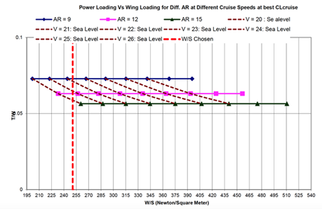
After analysing the defense and civil scenario, it is identified that the low altitude long endurance tactical section of UAV is the most lacking area. Such UAVs find application in border patrol, search and rescue, traffic monitoring, crowd control, environmental studies, asset monitoring, crop monitoring and re-supply. Initially, multiple configurations were designed and tested for attaining the design specifications. The most important of them were the wing loading and power loading, which was extensively studied. The results are summarized in Figure 1. |
|||||
|
|||||
|
|||||
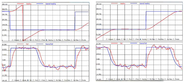
The control system provides integrated miniaturized avionics for autonomous control of micro/mini UAV, which is also capable of automatic take-off, landing, waypoint navigation and steering flight control with manual override. The MIL grade autopilot has integrated INS/GPS and Air data System provide accurate estimates of altitude, velocity and position. The versatile I/O interface provides option to hook up external payloads for user specific requirement. The integrated datalink modem provides communication in excess of 20 kms range. Users can dynamically plan mission, monitor critical flight parameters and adjust UAV parameters through an intuitive graphical user interface (GUI). The system performance was characterized and typical outcome is shown in Figure 3. |
|||||
|
|||||
 |
|||||
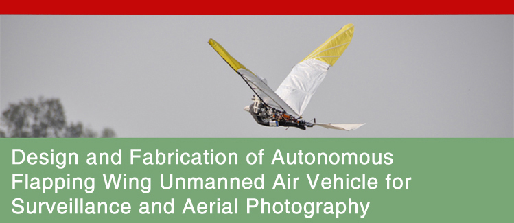
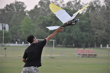
PI: Professor Debopam Das, Department of Aerospace Engineering Co-PI: Professor Abhishek, Department of Aerospace Engineering Professor K.S. Venkatesh, Department of Electrical Engineering Sponsor: IIT Kanpur and Prabhu Goel Foundation The project aims to build an autonomous 1.5 m wing span flying bird which will carry a small camera as the payload and will be able to record pictures for surveillance applications. Two other flying models have been constructed of wind span 1.6m with very distinct mechanisms and weight. The use of polythene wing membrane with density 40gm/m2 has proved to deliver superior performance. |
|||||
|
|||||
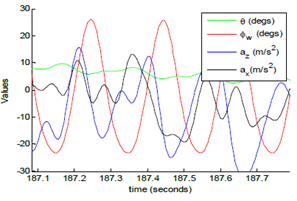
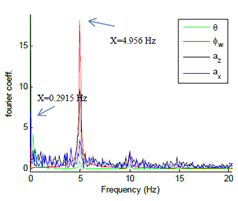
Technical Results Obtained: Flapping wing vehicle:
Autonomous flight test carried out on this model for loiter mode:
|
|||||
|
|||||
|
|||||
 |
|||||
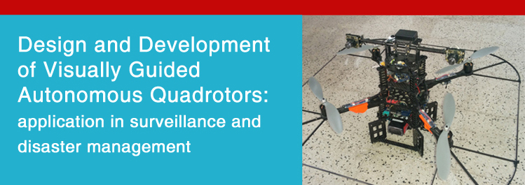
PI: Professor Laxmidhar Behera, Department of Electrical Engineering Co-PI: Professor Sumana Gupta, Department of Electrical Engineering Professor K.S. Venkatesh, Department of Electrical Engineering Professor Nishchal Verma, Department of Electrical Engineering Sponsor: IIT Kanpur and Prabhu Goel Foundation The need for unmanned aerial vehicles (UAVs) with greater maneuverability and hovering ability for various military and civilian applications has led to the current rise in quadrotor research. A quadrotor, also called a quadrotor helicopter or quad copter, is a multi-copter that is lifted and propelled by four rotors. The four-rotor design allows quadrotors to be relatively simple in design yet highly reliable, agile and maneuverable. |
|||||
|
|||||
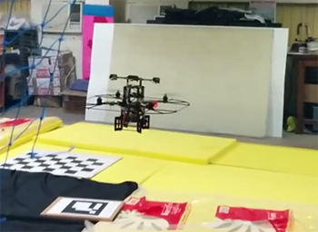 Figure 1: A quodrotor is hoovering based on visual feedback |
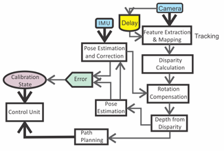
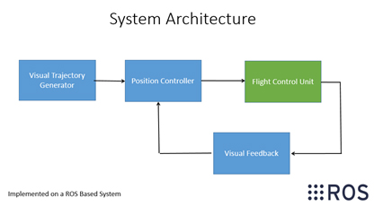 Figure 2: System architecture for Vision Based Navigation |
||||
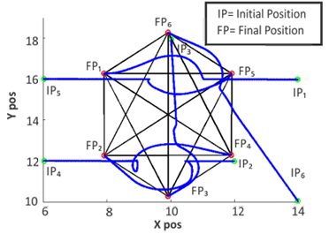
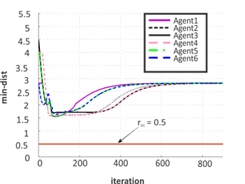
Stabilization of Multi-UAV systems and Formation Control Formation of quadrotors has great applications in precision agriculture, disaster management and crowd control. We consider an n-agent system where the agents move on a plane. Each agent communicates with its neighbours. The communication topology is fixed and is represented by a completely connected graph G. The objective of this work is to develop a control law to achieve a desired formation. The control law comprises of two parts: Improve collision avoidance scheme (ICAS) and consensus term. The ICAS has been designed to avoid collision between agents, and the consensus term helps in achieving the desired formation. We consider a 6-agent system to generate the collision free desired hexagon formation. Figure-4 is presented the trajectories of the six agents and from figure 5 it is observed that no agents collide with each other as the minimum inter agent distances never goes less than the safety distance rin=0.5. |
|||||
|
|||||
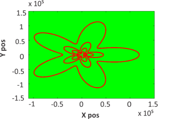
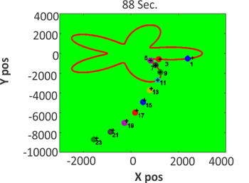
Static and Dynamic Boundary Estimation and Tracking: We consider 2n-agent system where the agents move on a plane. Each ith agent can communicate with its two neighbouring agents (Backward and Forward agents). The communication topology is fixed and is represented by a connected graph G. Each ith actual agent is associated with (i+1)th virtual agent (odd index is for actual agents and even index is for the corresponding virtual agent). The objective of this work is to develop a boundary tracking and estimation algorithm to track the static and dynamic boundary. In this work we are assuming that velocity of the dynamic boundary is less than the agent's velocity. We consider 24-agent system, where 12 are actual agents and 12-are virtual agents. Figure 6 presents the evolution of the dynamic boundary. From figure 7, it is observed that the agents are converging to the boundary. |
|||||
|
|||||
![]()
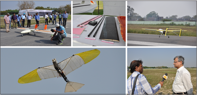
Open-house on UAV Technology The Indian Institute of Technology Kanpur along with the Prabhu Goel foundation has funded 3 projects titled Autonomous Flapping Wing Unmanned Air Vehicle, Fixed Wing Unmanned Aerial System and Visually Guided Autonomous Quadrotors in the area of UAVs. A unique open house demonstration of UAV technology was held on 27th March, 2015 at the Flight laboratory, IIT Kanpur. Working models of flapping wing bird, fixed wing unmanned aerial system and quadrotor were displayed during the demonstration. The progress of the projects was reviewed and appreciated by the subject experts.
|
Feedback/Suggestions
dord@iitk.ac.in |
Address for Correspondence
Dean, Research & Development http://www.iitk.ac.in/dord |