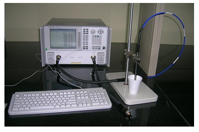
The dielectric measurement facility in the microwave frequency band was established in the Department of Electrical Engineering in the year 2010 with CARE grants from IIT Kanpur. The facility is based on the Agilent Technologies 85070E Dielectric Probe Kit, which comes along with the vector network analyzer and associated microwave components. The established facility enables one to determine the intrinsic electromagnetic properties of wide range of materials in the broad frequency range of 200 MHz to 20 GHz. As the dielectric properties of materials are related with their molecular structure, the measurement of dielectric properties leads to much other useful information which is otherwise quite difficult to obtain. These properties are usually expressed in terms of permittivity and permeability, which might change with frequency, temperature, orientation, mixture, pressure etc.
The electromagnetic characterization facility using the dielectric probe kit is currently installed in the Microwave Imaging and Material Testing Laboratory of the Electrical Engineering department as shown in the figure. The facility is expected to be used by departments of Civil Engineering, Bio Engineering, Material Science and Engineering, apart from the host department. The dielectric probe kit is one of the most useful methods for electromagnetic characterization of materials in the broad frequency range. The complete system is based on a network analyzer, which measures the material's response to RF or microwave energy. The probe transmits a signal into the material under test (MUT), and the reflected data is used to determine the dielectric properties of the MUT using special software, which is supplied along with the kit.
The probe supplied with the kit is quite versatile, and dielectric measurements can be carried out by simply immersing the probe into test liquids or semi-solids without requiring any special fixtures or containers. The procedure does not require any sample preparation, and the measurements are quite often non-destructive and can be made in real time. The software controls the network analyzer and guides the user through easy setup and measurement procedures. The complex permittivity of the test sample is finally displayed on screen of the network analyzer using the supplied software. The major components of the dielectric probe kit are as follows:
- Performance Probe
- Probe Stand
- 20 GHz PNA Series network analyzer
- Dielectric Probe Software
Performance Probe
The Performance Probe has many features such as ruggedness, high temperature and frequency performance in a slim design. The probe is sealed on both the probe tip and the connector end. The probe withstands a wide -40°C to +200°C temperature range. It is useful for measuring liquid, semi-solid as well as flat surfaced solid materials. The performance probe kit comes complete with a calibration short. The small diameter of the probe makes it possible to do measurement with small samples.
Probe Stand
The probe stand is used to hold the performance probe. The probe stand has 13 x 7 inch porcelain base and 24 inch high by 0.5 inch diameter metal support.
20 GHz PNA series vector network analyzer
The Vector Network Analyzer is quite versatile device, which includes a synthesized source, a wide dynamic range receiver, and a built-in test set. The Network Analyzer consists of two ports, a control panel, an information display and two RF cables to connect the device under test DUT with the analyzer. The types of these cables depend upon the frequency range of operation. One of the important steps in the measurement using Vector Network Analyzer is to do a proper calibration at the measurement reference planes. The calibration is usually done at the end of the test cables to eliminate any systematic errors occurring from the effects of the test fixture and its associated cables and hardware. The calibration procedure calculates the difference between measurement data of known calibration standards and ideal measurement data to create error correction array, which are then applied to actual measurements. The dielectric probe shown in the figure employs three calibration standards, which are air, a metal piece working as short, and water at room temperature in order to minimize the error during actual measurement.
Dielectric Probe Software
The dielectric probe kit shown in Fig. 1 comes with a software, which controls the network analyzer and guides the user through easy setup and measurement steps. The software may run on a PC or internally on the PNA series of Network Analyzer. The software controls the network analyzer to measure the complex reflection coefficient of the MUT (material under test). Then it converts the reflection coefficient into the complex permittivity of the MUT. Finally it displays the measurement results in a variety of graphical and tabular formats. The software also facilitates printing or plotting the results, saving the result in a number of formats. The software guides the user through normal "three standards calibration", which are short, open and water, performed at the end of the probe. After the probe calibration, the measurement of the actual test sample can be performed by either pressing the probe against the specimen (for solid samples), or by immersing the probe into the specimen (for liquid samples).