|
Experiment 5: Resonance in LCR Circuit. |
|
Resonance phenomenon in a series LCR circuits
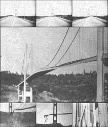
Mechanical Resonance in a bridge which finally breaks (source: http://www.lightandmatter.com/html_books/lm/ch18/ch18.html)
In physics, resonance is the tendency of a system to oscillate at a greater amplitude at some frequencies than at others. These are known as the system's resonance frequencies. At these frequencies, even small periodic driving forces can produce large amplitude oscillations, because the system stores vibrational energy. Resonance occur when a system is able to store and easily transfer energy between two or more different storage modes (such as kinetic energy and potential energy in the case of a pendulum). However, there are some losses from cycle to cycle, called damping. When damping is small, the resonant frequency is approximately equal to the natural frequency of the system, which is a frequency of unforced vibrations. Some systems have multiple, distinct, resonant frequencies.
In mechanical systems, when the forcing frequency nearly equals the natural frequency of vibration of the system (without the driving frequency) then the amplitude of vibrations become very large. See the example mechanical resonance setup in the bridge due to winds forcing the bridge. More details on resonance can be found at http://www3.wooster.edu/physics/jris/Files/Thaver.pdf http://en.wikipedia.org/wiki/Resonance#Electrical_resonance
Electrical resonance occurs in an electric circuit at a particular resonant frequency when the impedance of the circuit is at a minimum in a series circuit or at maximum in a parallel circuit (or when the transfer function is at a maximum).
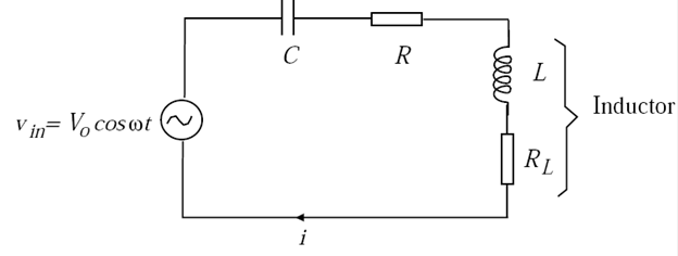
The phenomenon of resonance can be studied in an electrical system, viz., in a series RLC circuit
The impedance of this circuit is
We will assume RL is very small. The amplitude of voltage across R is
The impedance of the circuit is a minimum, and i and VR are a maximum when w0L = 1/w0C. Therefore resonance occurs at Resonance occurs at
The behavior of VR and f as a function of
The quality factor (Q) The bandwidth, Dw is defined as the difference between the frequencies w1 and w2 at which VR is 1/√2 = 0.707 of its peak value, and is given by
total series resistance:
At resonance, the impedance Z has a minimum value equal to the total series resistance in the circuit i.e. Z = R+RL, and the current through the circuit is a maximum, of amplitude I0 = V0/(R+RL). The impedance of the LC section is Z = RL+j(w0L−1/w0C) = RL at resonance, so the voltage across the LC section, VLC, will be 0 VR if RL << R. For an ideal inductor with RL = 0, VLC is also zero due to the exact cancellation of the equal but opposite-phase voltages across L and C.
Relevant links and where theory is discussed in details :
http://en.wikipedia.org/wiki/Resonance#Electrical_resonance http://hyperphysics.phy-astr.gsu.edu/hbase/electric/serres.html http://it.stlawu.edu/~jahncke/clj/cls/317/RLCResonance.pdf
Please feel free to send your feedback, suggestions or queries regarding the experiment to: oscillations.vlab@gmail.com In your email, please mention the experiment no. and name of the experiment. |


|
Developed and maintained by: Satyajit Banerjee, Pabitra Mandal and Gorky Shaw |
|
Procedure for downloading and running programs offline: · To download the programs, right click on the link above and choose ‘save target as’, or, ‘save link as’ depending on the browser. · Save the ‘.zip’ file to any directory on your PC. · Extract the ALL contents of the .zip file to the SAME folder. · Double click on the file “res_LCR.exe” to start executing the program. · After this, perform the experiment as demonstrated in the video instructions provided in the link below. |


