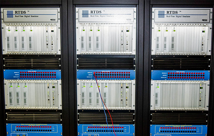
Real Time Digital Simulator(RTDS)
A six rack Real Time Digital Simulator (RTDS), facility supported by DST New Delhi under Intensification of Research in High Priority Areas (IRHPA) scheme, has been made operational since July 2011. The facility is located in ACES Building (ACES 105) in the Department of Electrical Engineering at IIT Kanpur.
With the advent of synchrophasor technology, the real time monitoring and control of power system has become possible. The major components of synchrophasor based WAMCS include PMUs, which provide voltage and current phasor information at a speed of 50/60 frames per second and the PDC situated at a control station.
Features
The IITK RTDS system is composed of 6 “racks” — each rack consisting of a number of parallel processing cards, including cards for running the simulation as well as inter-rack communications (IRC), workstation interface (WIF), and I/O cards. The PB5 processor card is the latest generation of processor card developed for the RTDS Simulator. Each PB5 has two PowerPC RISC processors operating at a clock frequency of 1.7 GHz. The increased clock frequency provides increased computing capacity compared to the GPC card.
One of the other significant new features provided by the PB5 is that it has eight (8) GT fibre ports. Two (2) GT ports are reserved for connecting to I/O and the other six (6) ports can be used to communicate directly to other PB5 or GPC cards.The increased number of ports will simplify the modeling of large scale systems using Small Timestep Subnetworks. This can be valuable for modeling distribution networks which have many short lines and can be difficult to model using a typical 50 µs timestep.
Each PB5 card has two Freescale MC7448 PowerPC RISC processors operating at a clock frequency of 1.7 GHz. The number of load units per processor has increased from 10 for the GPC to 12 for the PB5. This provides a 20% increase in computing capacity compared to the GPC card. This means that more components can be simulated using less hardware.
he number of nodes per network solution has increased from 66 single-phase nodes with the GPC processor card to 72 single-phase nodes (24 three-phase buses) with the PB5 processor card. Along with the node increase, perhaps the most significant feature of the PB5 processor card is its ability to support dual network solutions (i.e. two subsystems) in one rack. This means that the maximum number of nodes per rack is now 144 (2 x 72). As before, the subsystems must be split with a travelling wave transmission lines, cables or subsystem splitting transformer.
Hardware
The RTDS consists of individual racks of tightly coupled digital signal processors connected to each other using a common backplane. Each rack is identical and contains the following types of cards.
- Processor Card
- Workstation Interface Card (WIF)
- Inter Rack Communication (IRC) switch
The RTDS at IIT Kanpur contains PB5 processor cards and each rack contains three such cards. Each PB5 card contains two number of freescale MC7448 RISC processors and can operate at a clock speed of 1.7GHz. These cards contain 12 loading units, which allow more number of components to be included on one card. Each card can handle 72 single phase nodes or 24 three phase nodes and if each card is properly configured, it is able to simulate two networks (each of 72 nodes) simultaneously. PB5 cards are provided with 2 I/O ports and 6 communication ports, which will facilitate the user to communicate more number of other PB5 cards.
The simulator has been provided with Giga Transceiver Workstation Interface (GTWIF) card to perform communication between the RTDS and the host computer. Main functions of GTWIF include loading the case, starting and stopping the case, time stamp generation, rack hardware diagnostics, inter-rack synchronization along with IRC card. It works on 10/100 Base Tx Ethernet communications and facilitate USB access from the front panel for system diagnostics and configuration.
The simulator has been provided with Giga Transceiver Workstation Interface (GTWIF) card to perform communication between the RTDS and the host computer. Main functions of GTWIF include loading the case, starting and stopping the case, time stamp generation, rack hardware diagnostics, inter-rack synchronization along with IRC card. It works on 10/100 Base Tx Ethernet communications and facilitate USB access from the front panel for system diagnostics and configuration.
- GT I/O cards – used to export and import various electrical quantities and status of equipment in analog and digital forms. RTDS has been provided with GTDI card for digital input, GTDO card for digital output, GTAI card for analog input and GTAO card for analog output.
- GTNET cards – used to provide the real time communication link to and from the simulator to other hardware/software via Ethernet.
- GTNET – PMU to support C37.118 standard of PMU data,
- GTNET – GSE to communicate with IEC 61850 compliant IEDs with GSSE or GOOSE formatted,
- GTNET – SV to support IEC 61850-9-2 sampled value messaging for power system voltages and currents,
- GTNET – Playback to read large data files stored on a PC had disk and allow them to be played back in RTDS, and
- GTNET – DNP to support DNP 3.0, a SCADA protocol commonly used in substation.
- GTSYNC – used to synchronize the RTDS simulation time-step to GPS clock or some external reference.
The firmware versions supported by GTNET cards provided in RTDS are:
Software
RTDS software contains two components:
RTDS operating system and compiler- which runs on RTDS racks RTDS operating system (OS) runs in a distributed manner. One part of the OS runs on host computer of RTDS rack and other part runs on the GTWIF card. RTDS compiler converts simulations to the machine executable format. Compiler also takes care of parallel processing among digital signal processors, memory allocation and communication.
RSCAD A GUI based simulator to design and run the simulations RSCAD is a GUI based software tool to provide full graphical interface to RTDS. Draft module of RSCAD is used mainly for circuit assembly and parameter entry. The library section of draft module contains various pre-built power system and control components, which can be used to develop a simulation circuit in draft module. Runtime module of the RSCAD is used to control the simulation during run time, which runs on the RTDS racks. During runtime, various control operations such as fault application, breaker operation, and set point adjustment can be done using runtime module.
Once the compile process has been executed , the simulation can be run using RSCAD RunTime.
RunTime which operates on a window PC or Linux Workstation, communicate back and forth with the simulator's GTWIF cards via Ethernet.The bidirectional communication allows simulations to be downloaded and run as well as for simulation result to be transferred to the RunTime screen.The network can be operated from the RunTime by changing switching states or set points.
Communication protocols standard to power system industry
- IEC 61850 GOOSE (certified)
- SCD Editor
- IEC 61850-9-2 sampled values
- DNP3
- C37.118
International Electrotechnical Commission (IEC 61850) IEC 61850 defines 5 types of communication services. The first three types are time-critical and are used in protection and control schemes of the substation.They include Sampled Values (SV) and Generic Object OrientedSubstation Event (GOOSE) protocols which are mappeddirectly to Data Link layer for reduced protocol overhead and hence increased performance; and Generic Substation StateEvent (GSSE) protocol which features its own custom protocol mapping. The remaining two types of services, i.e., TimeSync and Client-Server Manufacturing Message Specification (MMS), deal with time synchronisation and management of the substation devices respectively.
IEC 61850 GOOSE (certified)
IEC 61850, the new communication standard for power substations, is now being widely used in practical applications. In particular, GOOSE (Generic Object Oriented Substation Events) messaging has been applied not only for SAS (Substation Automation System) control and monitoring of primary equipment and IED status, but also for status interactions between IEDs including protection relays by replacing the conventional method of using binary inputs/outputs and wires with communication by GOOSE messages over Ethernet cables/fibres.
- Standardized object models and naming conventions
- Standardized meaning of data
- Standardized services and device behavior models
- Self-describing devices
- Common configuration language
- Profiles for :-
- Control/SCADA
- Protection messaging
- Transducers and I/O
Distributed Network Protocol(DNP3)
DNP3 (Distributed Network Protocol) is a set of communications protocols used between components in process automation systems. Its main use is in utilities such as electric and water companies. Usage in other industries is not common. It was developed for communications between various types of data acquisition and control equipment. It plays a crucial role in SCADA systems, where it is used by SCADA Master Stations (aka Control Centers), Remote Terminal Units (RTUs), and Intelligent Electronic Devices (IEDs). It is primarily used for communications between a master station and RTUs or IEDs. ICCP, the Inter-Control Center Communications Protocol (a part of IEC 60870-6), is used for inter-master station communications.
IEEE C37.118 Synchrophasor Protocol (synchrophasor)
- The purpose of the C37.118 was to provide support for the development and use of synchrophasors in power systems. In it measurement requirements as well as methods for data exchange for using data in applications were developed.
- C37.118 describes a very simple, easy to implement data exchange system that can be used with many protocols. It has little overhead and can be implemented with a small processor system.
- IEEE C37.118 requires that the data frame as defined in the standard be transmitted in its entirety, including the cyclic redundancy check (CRC).It also specifies default port numbers for IP protocol; 4712 for TCP and 4713 for UDP.