
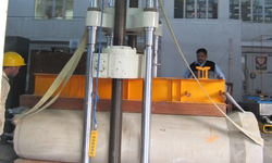
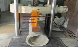
Accelerometer
- It is used to measure the acceleration of the structures. It is a four terminal and +5Volt DC operated device. It is generally manufactured for +/-2g or +/-10g acceleration measurement.

.jpg "Click to enlarge")
*Click image to enlarge
The table below shows the list of all the Accelerometer present at the Lab to be used for research and experimental testing.
S.NO. |
Model |
Serial No. |
Range (+/-) | Calibration (mv/g) |
Excitation (V DC) | Make |
DataSheet |
1 |
MA331 |
333467 |
10g |
3.05 |
5 |
SENSOTEC |
|
2 |
MA331 |
333468 |
10g |
2.84 |
5 |
SENSOTEC |
|
3 |
MA331 |
333469 |
10g |
3.07 |
5 |
SENSOTEC |
|
4 |
MA331 |
333470 |
10g |
2.68 |
5 |
SENSOTEC |
|
5 |
MA331 |
333471 |
10g |
2.56 |
5 |
SENSOTEC |
|
6 |
MA331 |
333472 |
10g |
2.92 |
5 |
SENSOTEC |
|
7 |
MA331 |
333473 |
10g |
2.56 |
5 |
SENSOTEC |
|
8 |
MA331 |
333474 |
10g |
3.42 |
5 |
SENSOTEC |
|
9 |
MA331 |
333475 |
10g |
3.42 |
5 |
SENSOTEC |
|
10 |
MA331 |
333476 |
10g |
3.17 |
5 |
SENSOTEC |
|
11 |
MA331 |
351952 |
10g |
4.54 |
5 |
SENSOTEC |
|
12 |
MA331 |
351953 |
10g |
4.38 |
5 |
SENSOTEC |
|
13 |
MA331 |
351954 |
10g |
4.32 |
5 |
SENSOTEC |
|
14 |
MA331 |
351955 |
10g |
4.48 |
5 |
SENSOTEC |
|
15 |
MA331 |
351956 |
10g |
4.07 |
5 |
SENSOTEC |
|
16 |
MA331 |
351957 |
10g |
4.27 |
5 |
SENSOTEC |
|
17 |
MA331 |
351958 |
10g |
4.42 |
5 |
SENSOTEC |
|
18 |
MA331 |
351959 |
10g |
4.61 |
5 |
SENSOTEC |
|
19 |
MA331 |
351960 |
10g |
4.4 |
5 |
SENSOTEC |
|
20 |
MA331 |
351961 |
10g |
4.46 |
5 |
SENSOTEC |
|
21 |
ICP |
10325 |
50g |
104.4 |
5 |
SENSOTEC |
|
22 |
FBA-II |
23242 |
1g |
2.5V/g |
12 |
KINEMETRICS |
|
23 |
FBA-II |
23243 |
1g |
2.5V/g |
12 |
KINEMETRICS |
|
24 |
FBA-II |
23244 |
1g |
2.5V/g |
12 |
KINEMETRICS |
|
25 |
FBA-II |
23245 |
1g |
2.5V/g |
12 |
KINEMETRICS |
|
26 |
FBA-II |
46739 |
1g |
2.5V/g |
12 |
KINEMETRICS |
|
27 |
FBA-II |
46740 |
1g |
2.5V/g |
12 |
KINEMETRICS |
|
28 |
393B04 |
5g |
18 to 13 |
PCB PIEZOTRONICS |
NOTE: Some relevent information regarding the MA331 model Accelerometer from Honeywell could be seen from the following PDF. (MA331) and for 393B04 model Accelerometer from PCB PIEZOTRONICS from the following PDF( 393B04 datasheet).
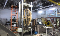
Extensometer
An extensometer is a device that is used to measure small/big changes in the length of an object. It is useful for stress-strain measurements. Its name comes from "extension-meter".For automated testing clip-on devices have been largely replaced by digital "feeler arm" extensometers.These can be applied to the specimen automatically by a motorised system and produce much more repeatable results than the traditional clip-on devices. They are counter balanced and so have negligible effect on the specimen. Better linearity, reduced signal noise and synchronisation with the corresponding force data are big advantages due to the lack of analogue to digital converters and associated filters which add time lags and smooth the raw data.

*Click image to enlarge
The table below shows the list of all the Extensometer present at the Lab to be used for research and experimental testing.
| S.NO. | Model | Serial No. | Excitation (VDC) | Guage Length | Travel (+/-) | Make | Data Sheet |
| 1 | 3543 | E86281 | 10 | 250mm | 50 | EPSILON | |
| 2 | 3542 | E82140 | 10 | 200mm | 12 | EPSILON | |
| 3 | 3542 | E82139 | 10 | 25mm | 5 | EPSILON | |
| 4 | 3543 | 10 | 25mm | 5 | EPSILON |
NOTE: Some relivent information regarding the model 3542 and 3543 from the Epsilon could be obtained from the following PDFs
Potentiometer
A potentiometer is a circuit element comprising a resistor which has a movable tap for adjusting the ratio of the resistances from the tap to the respective ends of the resistor. Linear potentiometers are useful to translate mechanical motion into responsive electrical signals. Linear potentiometers are devices that measure the relative movement between component parts of a machine, such as an injection molding machine. Linear refers to the mechanical direction of travel of the potentiometer slider as opposed to the electrical taper of the resistive element within the potentiometer. In order to provide accurate measurements, the potentiometer should be connected to the machine in such a manner that eliminates free play that could introduce measurement errors when the machine moves in a predetermined direction.

*Click image to enlarge
The table below shows the list of all the potentiometer present at the Lab to be used for research and experimental testing.
| S.NO. | TYPE | Serial No. | STROKE | Make | Data Sheet |
| 1 | CP (H) | 7973 | 200mm | UNI AUTOMATION | |
| 2 | CP (H) | 7974 | 200mm | UNI AUTOMATION | |
| 3 | CP (H) | 7975 | 200mm | UNI AUTOMATION | |
| 4 | CP (H) | 7976 | 200mm | UNI AUTOMATION | |
| 5 | CP (H) | 7977 | 200mm | UNI AUTOMATION | |
| 6 | CP (H) | 7978 | 200mm | UNI AUTOMATION | |
| 7 | CP (H) | 7979 | 200mm | UNI AUTOMATION | |
| 8 | CP (H) | 7980 | 200mm | UNI AUTOMATION | |
| 9 | CP (H) | 7981 | 200mm | UNI AUTOMATION | |
| 10 | CP (H) | 7982 | 200mm | UNI AUTOMATION | |
| 11 | CP (H) | 7983 | 200mm | UNI AUTOMATION | |
| 12 | CP (H) | 7984 | 200mm | UNI AUTOMATION | |
| 13 | CP (H) | 7985 | 200mm | UNI AUTOMATION | |
| 14 | CP (H) | 7986 | 200mm | UNI AUTOMATION | |
| 15 | CP (H) | 7987 | 200mm | UNI AUTOMATION | |
| 16 | CP (H) | 7988 | 200mm | UNI AUTOMATION | |
| 17 | CP (H) | 7989 | 200mm | UNI AUTOMATION | |
| 18 | CP (H) | 7990 | 200mm | UNI AUTOMATION | |
| 19 | CP (H) | 7991 | 200mm | UNI AUTOMATION | |
| 20 | CP (H) | 7992 | 200mm | UNI AUTOMATION |
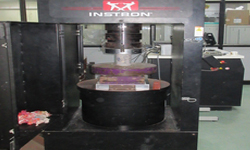
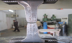
Load Cell
A load cell is an electronic device (transducer) that is used to convert a force into an electrical signal. This conversion is indirect and happens in two stages. Through a mechanical arrangement, the force being sensed deforms a strain gauge. The strain gauge converts the deformation (strain) to electrical signals. A load cell usually consists of four strain gauges in a Wheatstone bridge configuration.
A force transducer generally measures the applied force from the proportional deformation of a spring element: the larger the force, the more this element deforms. However, the frequency range of this type of transducer is limited by this element having to be sufficiently elastic to undergo large-amplitude deflections reflecting the load.


*Click image to enlarge
The table below shows the list of all the Loadcells present at the Lab to be used for research and experimental testing.
| S.NO. | Model | Serial No. | Excitation (VDC) | Calibration (mv/V) | CAP. (KG/KN) | TYPE | Make | DataSheet |
| 1 | 102 | 5AZ463 | 15 | 2 | 1000 KG | S | SENSOTEC | |
| 2 | 102 | 5AZ507 | 15 | 2.001 | 1000 KG | S | SENSOTEC | |
| 3 | 102 | 5AZ474 | 15 | 2.0027 | 1000 KG | S | SENSOTEC | |
| 4 | 102 | 5AZ442 | 15 | 2.0009 | 1000 KG | S | SENSOTEC | |
| 5 | 102 | 5AT148 | 15 | 2.001 | 1000 KG | S | SENSOTEC | |
| 6 | TH/1590-05 | 967551 | 10 | 2 | 500 KN | DONUT | SENSOTEC | |
| 7 | TH/1590-06 | 967552 | 10 | 2 | 500 KN | DONUT | SENSOTEC | |
| 8 | TH/1590-07 | 967553 | 10 | 2 | 500 KN | DONUT | SENSOTEC | |
| 9 | TH/1590-08 | 967554 | 10 | 2 | 500 KN | DONOT | SENSOTEC | |
| 10 | 43 | 1271803 | 10 | 2.9984 | 1500 KN | BUTTON | SENSOTEC | |
| 11 | 53A/G742-04 | 966131 | 10 | 4 - 20mA | 100 KN | BUTTON | SENSOTEC | |
| FORCE TRANSDUCER | ||||||||
| 1 | 661.22D-01 | 203 | - | - | 280000 N | - | MTS | |
| ULTRA PRECISION PRESSURE TRANSDUCER | ||||||||
| 1 | Super TJE | Honey well | ||||||
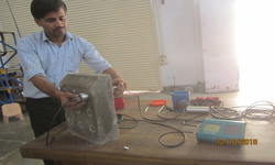
LVDT (Linear Variable Differential Transformer)
It is a basically transducer that gives us voltages by changing the displacements. LVDT is a five terminal DC Voltage operated device, where its three terminals are used to give the floating excitation to it and other two are used to measure potential.

*Click image to enlarge
The table below shows the list of all the LVDT present at the Lab to be used for research and experimental testing.
| S.NO. | Model No. | Serial No. | Excitation (V) | Calibration (V/mm) | Range (+/-) | Make | Data Sheet |
|---|---|---|---|---|---|---|---|
| 1 | JEC-AG | 11256800 | 40 | 0.0983 | 50 mm | SENSOTEC | |
| 2 | JEC-AG | 11256900 | 40 | 0.0968 | 50 mm | SENSOTEC | |
| 3 | JEC-AG | 11257000 | 40 | SEND FOR REPAIR | 50 mm | SENSOTEC | |
| 4 | JEC-AG | 11257100 | 40 | 0.0978 | 50 mm | SENSOTEC | |
| 5 | JEC-AG | 11257200 | 40 | SEND FOR REPAIR | 50 mm | SENSOTEC | |
| 6 | JEC-AG | 11257300 | 40 | SEND FOR REPAIR | 50 mm | SENSOTEC | |
| 7 | JEC-AG | 11257400 | 40 | 0.0983 | 50 mm | SENSOTEC | |
| 8 | JEC-AG | 11257500 | 40 | 0.0960 | 50 mm | SENSOTEC | |
| 9 | JEC-AG | 11257600 | 40 | SEND FOR REPAIR | 50 mm | SENSOTEC | |
| 10 | JEC-AG | 11257700 | 40 | SEND FOR REPAIR | 50 mm | SENSOTEC | |
| 11 | JEC-AG | L12451100 | 40 | 0.09842 | 50 mm | SENSOTEC | |
| 12 | JEC-AG | L12451200 | 40 | 0.09842 | 50 mm | SENSOTEC | |
| 13 | JEC-AG | L12451400 | 40 | 0.09842 | 50 mm | SENSOTEC | |
| 14 | JEC-AG | L11624100 | 40 | 0.09645 | 50 mm | SENSOTEC | |
| 15 | 10 | 66.8 | 50 mm | SOLARTRON | |||
| 16 | 10 | 183.7 | 25 mm | SOLARTRON | |||
| 17 | 10 | 63.5 | 50 mm | SOLARTRON | |||
| 18 | 10 | 60.6 | 50 mm | SOLARTRON | |||
| 19 | 10 | 192 | 25 mm | SOLARTRON | |||
| 20 | 10 | 10 | 50 mm | SOLARTRON | |||
| 21 | DCTH 6000A | 29386 | 15V DUAL | 32.43 | 150 mm | SOLARTRON | |
| 22 | DCTH 6000 | 29388 | 15V DUAL | 32.12 | 150 mm | SOLARTRON | |
| 23 | DCTH 3000A | 35703 | 15V DUAL | 64.79 | 75 mm | SOLARTRON | |
| 24 | DCTH 3000A | 35704 | 15V DUAL | 64.62 | 75 mm | SOLARTRON | |
| 25 | DFG -1 | M920154A322-04 | 10 | 76.72 | 1 mm | SOLARTRON | |
| 26 | DFG -1 | M920154A322-02 | 10 | 74.739 | 1 mm | SOLARTRON | |
| 27 | DFG -1 | M920154A322-01 | 10 | 74.85 | 1 mm | SOLARTRON | |
| 28 | DFG -1 | M920154A322-03 | 10 | 76.49 | 1 mm | SOLARTRON | |
| 29 | DFG -2.5 | M920016A322-03 | 10 | 76.32 | 2.5 mm | SOLARTRON | |
| 30 | DFG -2.5 | M920016A322-01 | 10 | 78.01 | 2.5 mm | SOLARTRON | |
| 31 | DFG -2.5 | M920016A322-04 | 10 | 76.23 | 2.5 mm | SOLARTRON | |
| 32 | DFG -2.5 | M920016A322-02 | 10 | 76.82 | 2.5 mm | SOLARTRON | |
| 33 | DFG -5 | M920017A322-03 | 10 | 52.65 | 5 mm | SOLARTRON | |
| 34 | DFG -5 | M920017A322-04 | 10 | 53.26 | 5 mm | SOLARTRON | |
| 35 | DFG -5 | M920017A322-02 | 10 | 53.46 | 5 mm | SOLARTRON | |
| 36 | DFG -5 | M920017A322-01 | 10 | 53.34 | 5 mm | SOLARTRON |
NOTE: Some relivent information regarding the Sensotec LVDT from honeywell could be found from the following PDF (SENSOTEC LVDT)
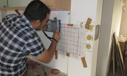
Strain Gauges
A strain gauge is a device used to measure the strain of an object. The gauge is attached to the object by a suitable adhesive, such as cyanoacrylate. As the object is deformed, the foil is deformed, causing its electrical resistance to change. This resistance change, usually measured using a Wheatstone bridge, is related to the strain by the quantity known as the gauge factor.

*Click image to enlarge
The following types of strain gauges are available in the laboratory :
| S.no. | Type | Gauge length | Resistance | Datasheet | Image |
| 1 | Foil Type | 3.175 mm | 350 ohms | click | |
| 2 | Rossette | 6.35 mm | 350 ohms | click |
Note:
- The Strain Gauge installation guide could be found at the following link -- Click Here
